How to Extend Video Intercom Cable Distance Beyond 100 Meters: Solutions and Best Practices
Share
The 100-meter limit on standard Ethernet copper cabling is not a suggestion—it is an engineering boundary defined by signal attenuation, crosstalk, and the physical layer specifications of the Ethernet standard. When a villa gate, a detached garage, or a perimeter entrance sits beyond that boundary, simply adding a longer cable will not solve the problem. What is required is a different transmission architecture.
This guide explains why the 100-meter limit exists, compares the four viable methods for extending video intercom distance, and sets out the practical considerations that determine which method is appropriate for a given project.
Why 100 Meters Is a Hard Limit, Not a Soft Guideline
Copper Ethernet transmits data as electrical signals. As cable length increases, conductor resistance, capacitance, insertion loss, and crosstalk progressively degrade signal quality. The 100-meter figure represents the maximum channel length over which standard Ethernet can reliably operate under structured cabling conditions—including patch cords, connectors, and installation tolerances.
For PoE devices—which include most modern IP video intercoms—the constraint is compounded. The same cable must carry both data and power. Longer runs increase voltage drop, and the power delivered at the far end may fall below what the device requires to boot or operate reliably. The problem is not merely “can the data travel?” but “can the device receive sufficient power at the destination?”
Quick Comparison: Four Methods for Extending Video Intercom Distance
| Method | Typical distance | Power delivery | Best for | Key constraint |
|---|---|---|---|---|
| 2-Wire to IP converter | 220 m typical; up to 750 m possible | PoE power over 2-wire | Retrofits with existing 2-wire cabling | Requires converter pair; polarity matters |
| PoE extender / Ethernet extender | 400–1,000+ m depending on device | PoE power extended over copper | Point-to-point runs with existing copper | Distance and bandwidth vary by device and cable |
| Fiber optic link | 300 m (multimode); many km (single-mode) | No PoE through fiber; local power required at far end | Long runs, electrical isolation, high bandwidth | Requires media converters and local power |
| Wireless bridge | 100–500 m depending on technology | Local power at both ends | Sites where cabling is impractical | Line-of-sight and RF environment dependent |
Method 1: 2-Wire to IP Converter – The Retrofit Path
A 2-wire to IP converter pair allows an IP video intercom to operate over existing legacy two-core cabling—such as old telephone wire or analog intercom cable—while preserving full IP functionality, including PoE power delivery.
How it works. One converter unit (“leader”) connects to the network switch via Ethernet and to the legacy 2-wire cabling. The second unit (“follower”) connects to the IP intercom at the remote location. The pair transmits Ethernet data and PoE power over the two-core cable.
Distance. Typical performance is 220 metres at Cat6 with PoE at the far end; up to 750 metres is possible depending on wiring quality and electromagnetic environment. Separate converter products on the market specify transmission distances of up to 600 metres over 2-wire cable.
Critical installation notes. Polarity must be observed on the 2-wire connection—positive to positive, negative to negative. The leader unit should not be connected to a PoE port on the switch; if only PoE ports are available, PoE must be disabled on that port. Up to three follower units can be connected to a single leader in some configurations.
When to choose this method. The 2-wire converter is the correct choice when the building already has usable two-core cabling and the project requires IP functionality without the cost and disruption of new cable installation. It is a retrofit solution, not a general-purpose extender.
Method 2: PoE Extender / Ethernet Extender – Extending Copper Beyond 100 Meters
A PoE extender is a powered device that sits in-line on the copper cable, receiving Ethernet data and PoE power from the switch and re-transmitting both to the remote device over an additional cable segment. This effectively resets the 100-meter “clock” for each segment.
Distance. Performance varies significantly by product. Industrial-grade PoE extenders on the market specify distances of 400 metres, 1,005 metres over 2-wire or coaxial cable, and up to 1.8 kilometres over coaxial cable in specialised configurations. The distance achieved depends on the extender’s physical-layer technology, the cable type and gauge, and the power requirements of the remote device.
Bandwidth trade-offs. Some long-reach PoE extension methods reduce link speed. A common manufacturer “extend mode” may drop the link to 10 Mbps to achieve distances beyond 100 metres. For video intercoms transmitting HD video, this bandwidth reduction may be acceptable for a single door station but must be verified against the camera’s stream bitrate.
When to choose this method. PoE extenders are appropriate for point-to-point runs where existing copper is present, the device count is low, and the installer wishes to avoid the cost of fibre termination equipment. They are less suitable for aggregating multiple devices at the far end, where a remote PoE switch or fibre link may be more efficient.
Method 3: Fiber Optic Link – The Long-Distance and Electrical-Isolation Option
Fiber carries data as light rather than electrical signals. This eliminates the distance limitations of copper and provides electrical isolation between the two endpoints—a significant advantage for outdoor intercoms exposed to lightning and ground-potential differences.
Distance. Multimode fibre supports up to 300 metres; single-mode fibre supports point-to-point distances of many kilometres. For video intercom applications, a fibre run can terminate at a PoE media converter when one or two devices require service at the remote end.
The critical limitation: fiber does not carry PoE. The remote intercom requires local power at the far end of the fibre link. This means a power outlet or a local power supply must be available at the gate or remote entrance. If no power exists at the remote location, fibre alone will not solve the problem.
When to choose this method. Fibre is the correct choice for distances beyond 300 metres, for building-to-building links where electrical isolation is required, or for projects where the highest bandwidth and future capacity are priorities. It is not a PoE solution—it is a data-transport solution that must be paired with local power.
Method 4: Wireless Bridge – When Cabling Is Not Feasible
A wireless bridge uses a dedicated point-to-point or point-to-multipoint RF link to connect the remote intercom to the network without any cable between the two locations.
Distance and technology. Wireless performance varies by frequency and technology. Wi-Fi HaLow operating on the 866 MHz band has been specified for up to 500 metres in open areas. Standard Wi-Fi bridges may achieve shorter distances and are more susceptible to interference.
Constraints. Wireless requires line-of-sight in most practical installations and is affected by RF interference, weather, and physical obstructions. Power is required at both ends of the link. For a video intercom, the wireless link must have sufficient and stable bandwidth to carry both the video stream and the control signalling without introducing latency or dropouts.
When to choose this method. Wireless is appropriate when trenching or cable installation is physically impossible or prohibitively expensive, and when a reliable line-of-sight path exists. It should not be treated as a default solution for long-distance intercom connectivity.
What About Standard 2-Wire Intercoms Without IP?
A standard 2-wire video intercom—one that is not IP-based—can also extend beyond 100 metres, but the limiting factor is different: voltage drop and cable gauge, not Ethernet’s data-layer rules.
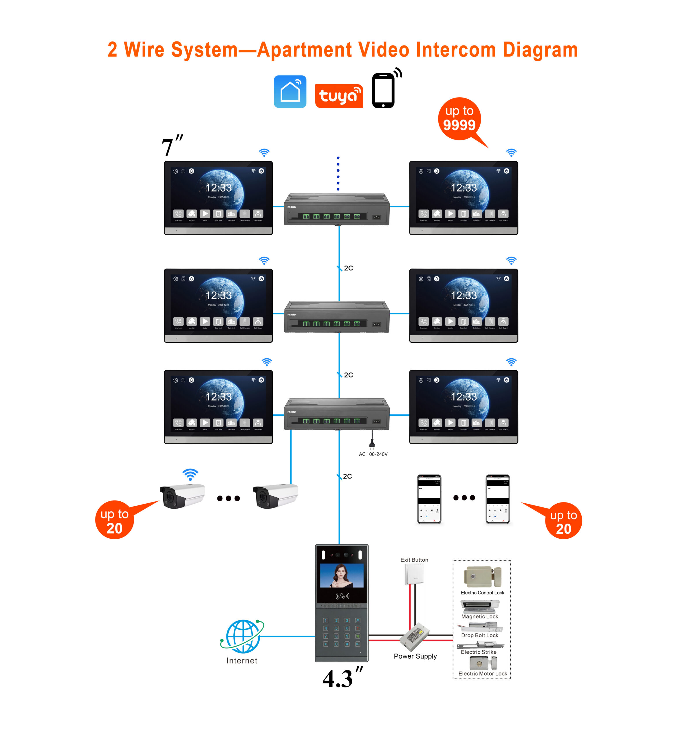
For 48V 2-wire systems, the achievable distance depends on conductor size and the number of devices on the line. At AWG24 (0.51 mm), the maximum distances are approximately 100 m for 6 devices, 150 m for 4 devices, and 200 m for 3 devices. At AWG20 (0.81 mm), distances increase to 250 m for 6 devices and 300 m for 5 devices. At AWG18 (1.02 mm), 300 m for 6 devices is achievable. These figures apply to daisy-chained 2-wire systems; the number of monitors in a single chain is typically limited to six, with additional hubs required for more.
The practical implication is that a non-IP 2-wire intercom can be extended beyond 100 metres by increasing conductor gauge and reducing the number of devices on the run—but the solution is a cable and topology change, not a signal-extension device.
Best Practices for Any Long-Distance Intercom Installation
Measure the actual route, not the straight-line distance. Cable routes follow walls, trenches, and conduits. The as-built length is almost always longer than the architectural dimension.
Calculate power budget before data budget. For PoE devices, confirm that the power delivered at the far end exceeds the intercom’s minimum operating voltage and current. PoE extension and long copper runs both increase losses.
Do not cascade extenders without testing. Each extension device adds latency and a potential failure point. For distances beyond the rated limit of a single extender, fibre is generally more reliable than a chain of copper extenders.
Separate data and power planning for fibre. Fibre solves the data-distance problem but does not solve power. Confirm that a power source exists at the remote end before selecting a fibre solution.
Test the unlock function at maximum distance. Video and audio may appear acceptable while the relay or lock-release signal degrades. Always verify the unlock function at the far end of the run, not just the video feed.
Document the architecture. Record cable types, converter models, power supplies, and segment lengths. A long-distance link is more sensitive to changes in any single component, and documentation is essential for future maintenance.
FARHD’s Position in Long-Distance Intercom Deployments
FARHD’s 2-wire IP and PoE intercom systems are designed for projects where existing cabling or structured network infrastructure is the starting point. The 2-wire non-polarity architecture is intended for retrofits where two-core cabling is present, and the IP models support PoE where Cat5e/6 infrastructure is available. For projects where the distance exceeds the native capability of either architecture, the appropriate solution is determined by the site conditions: existing copper, available power, bandwidth demand, and whether electrical isolation is required. The relevant question is not which extension method is “best,” but which method matches the physical and electrical constraints of the specific installation.

About the Author: S & Y Internet Technology Inc.
S & Y Internet Technology Inc. is a professional installation and repair service provider based in Flushing, New York. Our expert team provides door-to-door installation and maintenance within a 100 km radius, ensuring quick response and high-quality results for every project — whether residential, commercial, or specialized.

Install & Repair Services
You May Also Interest
-
Video Intercom Power Supply Options Explained: PoE, 2-Wire, Battery and Solar
Video intercom power supply is not a single decision. It is a cascade of decisions that begins with the building’s existing wiring and ends with how much maintenance the owner is willing to accept over the system’s life. PoE, 2-wire, battery, and solar are not four variations of the same solution. They serve different installation…
-
Video Intercoms for Historic Buildings: How to Modernize Access Without Damaging Heritage Architecture
The Governing Constraint: Fabric First, Technology Second Conservation regulations in most heritage jurisdictions prohibit visible cables, surface-mounted conduits, and devices that would alter the character of the building. Drilling into stone façades, ornate woodwork, or antique brickwork is treated as permanent damage, not a maintenance task. This means the technology stack must be chosen not…
-
From Inquiry to Installation: A Buyer’s Journey for Apartment Video Intercom Projects
Sourcing a video intercom system for an apartment building is a multi-stage process. It begins with a simple inquiry and ends with a fully operational system protecting residents and streamlining access. For distributors, system integrators, and property developers, understanding this journey is essential to avoiding delays, cost overruns, and installation headaches. This guide walks you…
-
How to Evaluate Video Intercom Suppliers: Quality, Certifications, and After-Sales Support
Choosing the right video intercom supplier is not just a purchasing decision—it is a long-term partnership that affects your product quality, your margins, and your reputation. This guide explains how to evaluate suppliers on three critical dimensions: quality, certifications, and after-sales support. In the global video intercom market, hundreds of suppliers claim to be manufacturers….