Apartment Video Intercom System Installation Guide: Outdoor Station, Indoor Monitor and Network Setup
Share
Installing a video intercom system in an apartment building might seem like a complex project, but with the right planning and a clear, step-by-step approach, it’s a manageable task. This guide provides a comprehensive walkthrough for installing a typical apartment video intercom system, covering everything from mounting the hardware to configuring the network.
1. Before You Begin: Planning & Preparation
Proper planning is the cornerstone of a successful installation. Taking the time to prepare will save you significant headaches later.
1.1. Choose Your System Type
The first and most crucial step is selecting the right system for your building’s infrastructure. Your choice will dictate the wiring and installation process.
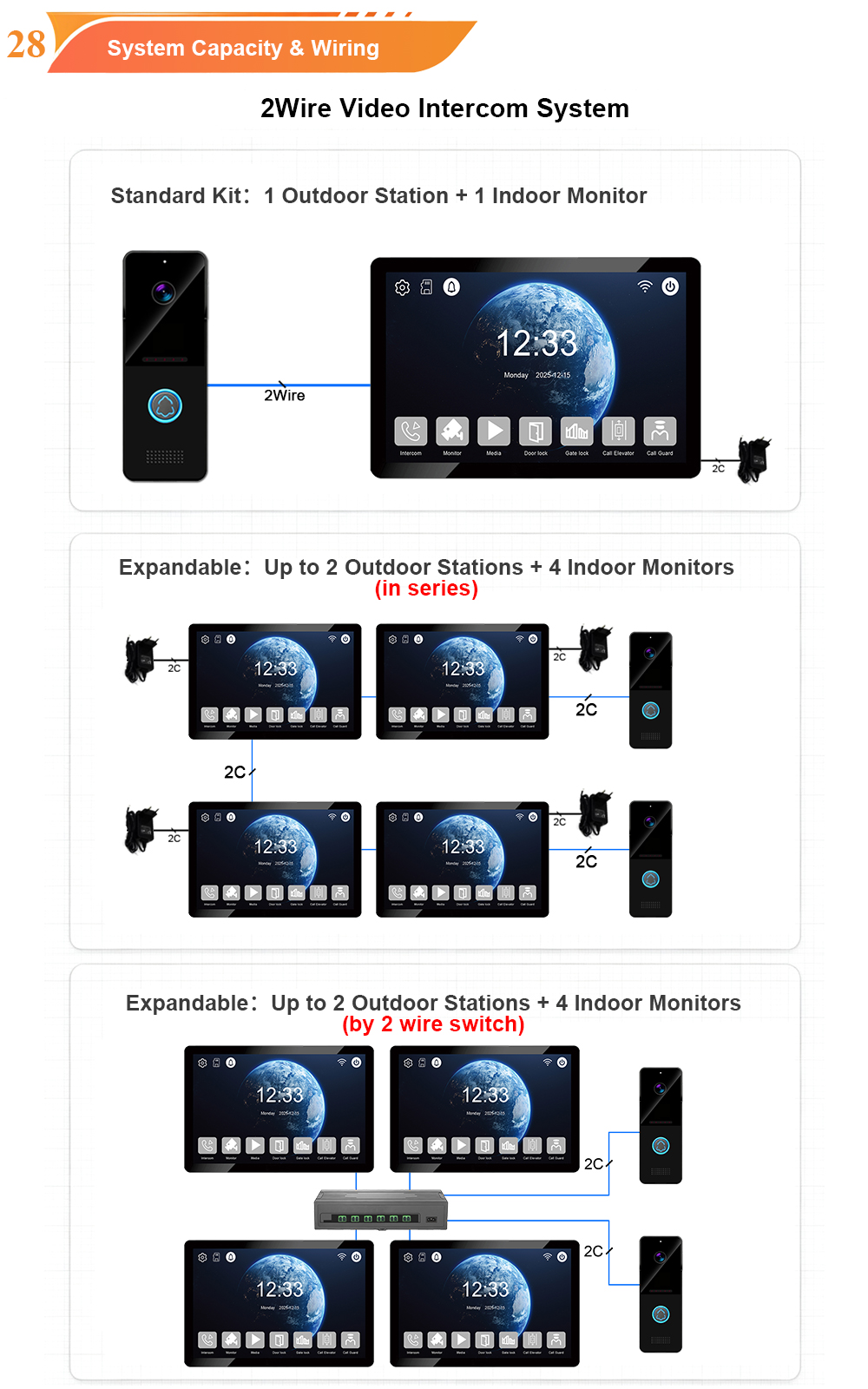
- 2-Wire Systems: Ideal for retrofitting older buildings. They reuse existing two-core cables (like old doorbell or telephone wires), significantly reducing installation time, cost, and wall damage. The 2-wire technology transmits power, video, audio, and control signals over a single pair of wires.
- 4-Wire Systems: A standard for traditional analog installations. They use separate wires for power and signal, offering a stable and interference-free connection, especially over longer distances.
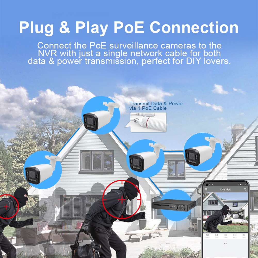
- IP Systems: The modern standard for new builds. They use standard CAT5/6 network cables, often with Power over Ethernet (PoE) to supply power and data through a single cable. This provides the most flexibility, scalability, and features like remote access and app integration.
1.2. Gather Your Tools and Components
Before starting, ensure you have the necessary tools and components.
- Key Components:
- Tools:
- Drill and appropriate bits (masonry for brick/concrete, wood for timber).
- Screwdrivers (Phillips and flathead).
- Wire strippers and cutters.
- Level.
- Pencil or marker.
- For IP systems: A laptop or computer for network configuration and a network switch (PoE if needed).
2. Installing the Outdoor Station (Door Station)
The outdoor station is the visitor’s first point of contact and needs to be installed securely and conveniently.
2.1. Choose the Location
Select a location near the main entrance. The ideal height is typically 1.4 to 1.7 meters (about 4.5 to 5.5 feet) from the ground. This ensures optimal viewing of visitors’ faces and protects the unit from damage.
- Avoid Direct Sunlight: Position the camera to avoid direct sunlight, which can cause glare and poor image quality.
- Consider Weather Protection: Install the unit under an eave or use a rain cover (if not built-in) to protect it from heavy rain and snow.
2.2. Mount the Unit
- Mark the Mounting Points: Hold the mounting bracket against the wall at your chosen location and use a pencil to mark the screw holes. Use a level to ensure it’s straight.
- Drill Pilot Holes: Drill holes at the marked points. Use a drill bit appropriate for your wall type.
- Secure the Mounting Bracket: Attach the bracket to the wall using the provided screws and wall plugs.
- Attach the Outdoor Station: Following the manufacturer’s instructions, connect the wiring to the outdoor station terminals and then attach the unit to the bracket.
2.3. Wiring Connections
- 2-Wire/4-Wire Systems: Connect the appropriate cable from the indoor monitor to the outdoor station terminals. The connection is often non-polarity for 2-wire systems (you can connect the wires either way).
- IP Systems: Connect a CAT5/6 cable from the outdoor station’s RJ45 port to your network switch or PoE switch.
3. Installing the Indoor Monitor(s)
The indoor monitor is the primary interface for residents. Its installation is generally more straightforward.
3.1. Choose the Location
Select a convenient indoor location, such as a hallway, living room, or kitchen. It should be in a central area where the ringtone can be easily heard and the monitor is easily accessible.
3.2. Mount the Monitor
- Mark the Mounting Points: Hold the indoor monitor’s mounting bracket against the wall at your chosen location and mark the screw holes. Use a level to ensure it’s straight.
- Drill Pilot Holes: Drill holes at the marked points.
- Secure the Mounting Bracket: Attach the bracket to the wall using the provided screws and wall plugs.
- Attach the Monitor: Following the manufacturer’s instructions, connect the wiring and then attach the monitor to the bracket.
3.3. Wiring Connections
- 2-Wire/4-Wire Systems: Connect the cable from the outdoor station to the designated terminals on the indoor monitor. This single cable often provides both power and communication.
- IP Systems: Connect a CAT5/6 cable from the indoor monitor to your network switch or PoE switch. For IP systems, the indoor monitor gets its power and data from the same network cable.
4. Network Setup (For IP Systems)
IP systems require network configuration to ensure all devices communicate correctly.
4.1. Connect to the Network
- Connect to Switch: Ensure all IP devices (outdoor station, indoor monitors) are connected to the same network switch.
- Power On: Power on the network switch. The devices should power up automatically if using PoE.
4.2. Configure the Outdoor Station
- Find the Device: Use the IP Manager Tool (or similar software provided by the manufacturer) on a computer connected to the same network to locate the outdoor station.
- Set the IP Address: Depending on your network requirements, you can assign a static IP address or let the device obtain one automatically via DHCP.
- Configure Settings: Set the device as an “Outdoor Station” in the configuration tool.
4.3. Configure the Indoor Monitor(s)
- Find the Device: Use the IP Manager Tool to locate the indoor monitor(s) on the network.
- Assign Room Numbers: Assign each indoor monitor a specific apartment number or ID in the configuration. This links the monitor to the correct call button on the outdoor station.
- Configure Settings: Set the device as an “Indoor Station” in the configuration tool.
5. System Testing & Configuration
After all hardware is installed and connected, it’s time to power on and test the system.
5.1. Power On and Test
- Power Up: Turn on the power supply to the system. For analog systems, this is usually the indoor monitor’s power adapter. For IP systems, ensure the PoE switch is powered on.
- Perform a Call Test: Press the call button on the outdoor station. The corresponding indoor monitor should ring and display the video feed.
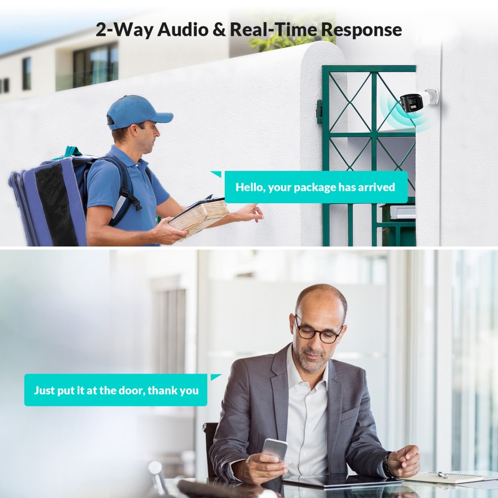
- Test Two-Way Audio: Answer the call from the indoor monitor and test the two-way audio communication.
- Test the Door Unlock: While on the call (or from the monitor’s main menu), press the unlock button. The door lock should release.
5.2. Additional Features
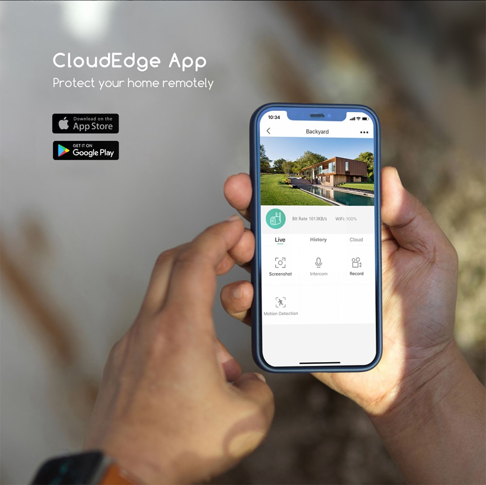
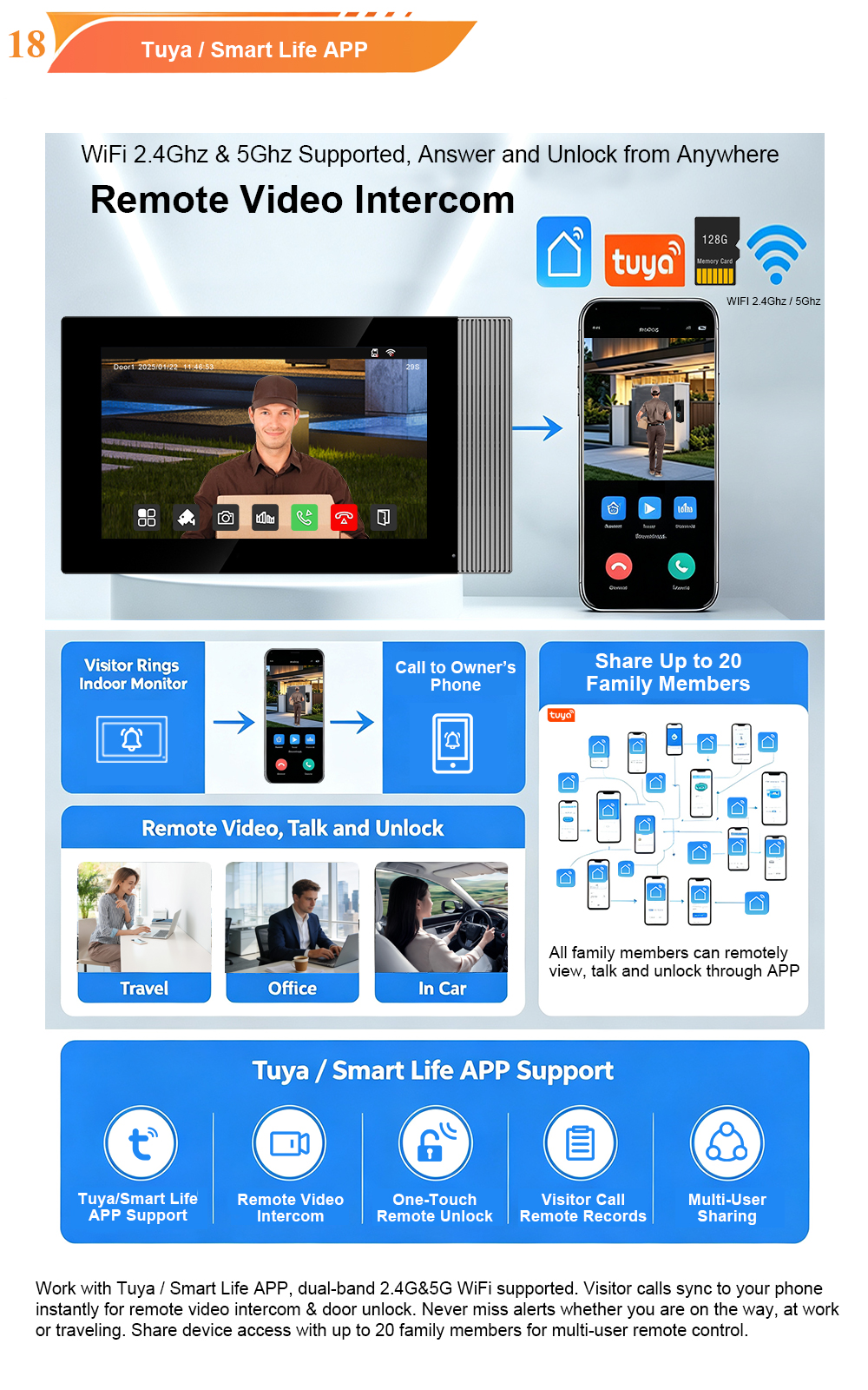
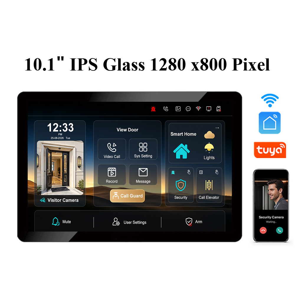
- Mobile App Configuration: If your system supports remote access (like Tuya/Smart Life), configure the app by scanning a QR code or following the manufacturer’s instructions. This allows residents to answer calls and unlock doors from their smartphones.
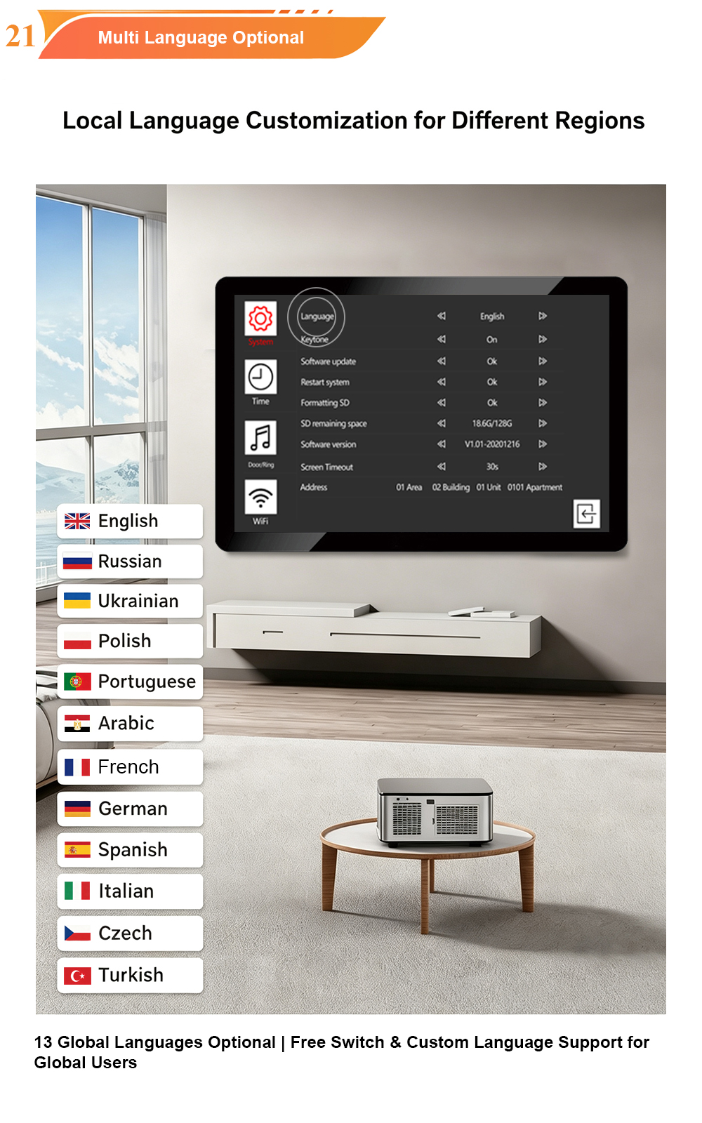
- Multi-Language Settings: Most modern systems offer multi-language support. Navigate to the settings menu on the indoor monitor to select the preferred language for the user interface.
Common Installation Issues & Troubleshooting
- No Power / No Display: Check the power connections. For 2-wire systems, verify the indoor monitor’s power adapter is plugged in. For IP systems, confirm the PoE switch is supplying power to the device.
- No Video or Poor Video: Check the wiring connections for loose cables or incorrect polarity (for 4-wire systems). For IP systems, verify the network cable is properly connected and the device has a valid IP address.
- No Audio: Check the volume settings on the indoor monitor. Verify the speaker and microphone are not obstructed.
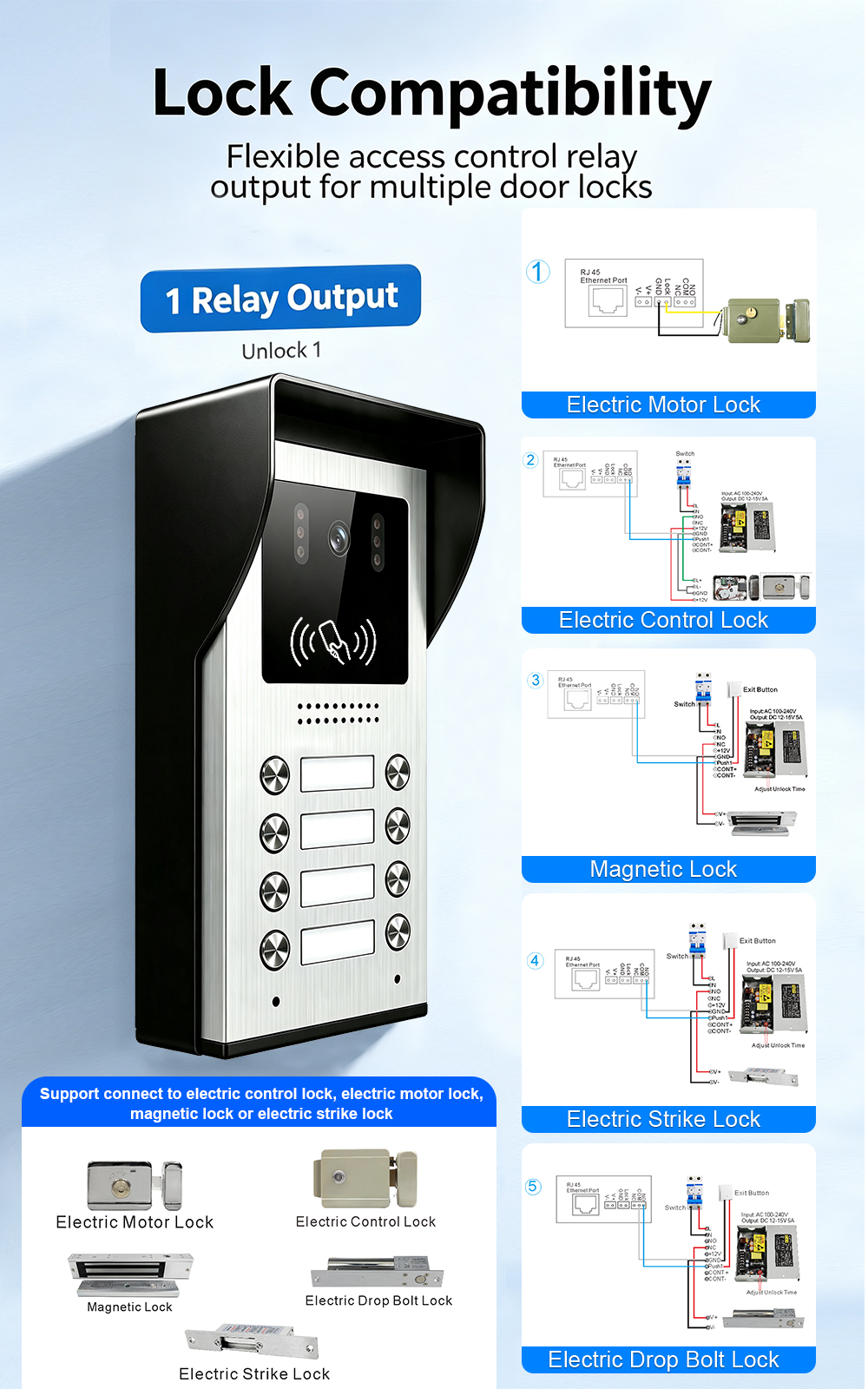
- Door Lock Doesn’t Release: Ensure the lock is compatible with your system and that it has its own dedicated power supply (most systems only provide a dry contact relay, not direct power to the lock).
Conclusion
Installing a video intercom system in an apartment building is a significant upgrade that dramatically improves security and convenience. Whether you’re working with a simple 2-wire system or a full IP network, the installation process involves careful planning, proper mounting, and systematic testing. By following this guide and your system’s specific manual, you can ensure a reliable installation that will serve your building for years to come.

About the Author: S & Y Internet Technology Inc.
S & Y Internet Technology Inc. is a professional installation and repair service provider based in Flushing, New York. Our expert team provides door-to-door installation and maintenance within a 100 km radius, ensuring quick response and high-quality results for every project — whether residential, commercial, or specialized.

Install & Repair Services
You May Also Interest
-
RFID vs QR Code vs Mobile App: Comparing Access Methods for Residential Buildings
Choosing the right access method for your apartment building or gated community is a decision that affects security, convenience, cost, and resident satisfaction. RFID cards, QR codes, and mobile apps each have distinct strengths and weaknesses. This guide compares them side by side—so you can make an informed choice for your next project. In modern…
-
Tuya vs Smart Life: Which App Is Better for Your Video Door Phone?
A practical comparison to help you choose the right app for your smart intercom system If you’ve recently purchased a FARHD video door phone, you’ve probably noticed that the product documentation mentions two apps: Tuya Smart and Smart Life. This immediately raises a common question: which one should you actually use? Are they different? Does…
-
Touch Screen vs Non-Touch Video Intercom Monitors: Which Is Better for Residents?
When specifying a video intercom system for an apartment building, villa, or residential community, one question often divides decision-makers: should the indoor monitor have a touch screen or physical buttons? Both options have passionate advocates. Both have real advantages. And both can be the wrong choice if they don’t match the needs of the residents…
-
How to Upgrade an Old Apartment Intercom to IP Without Rewiring: Step-by-Step
Upgrading an old apartment intercom to a modern IP system no longer requires tearing down walls, replacing every cable, or disrupting residents for weeks. With the right retrofit technology, you can deliver full IP functionality—video calling, mobile access, remote management—using the existing 2-wire cabling already inside your building. This step-by-step guide shows you how. Many…